Schematic design of the pcb test board for testing the proposed sensor Circuit board design for in-circuit testers Schematic help wether downside
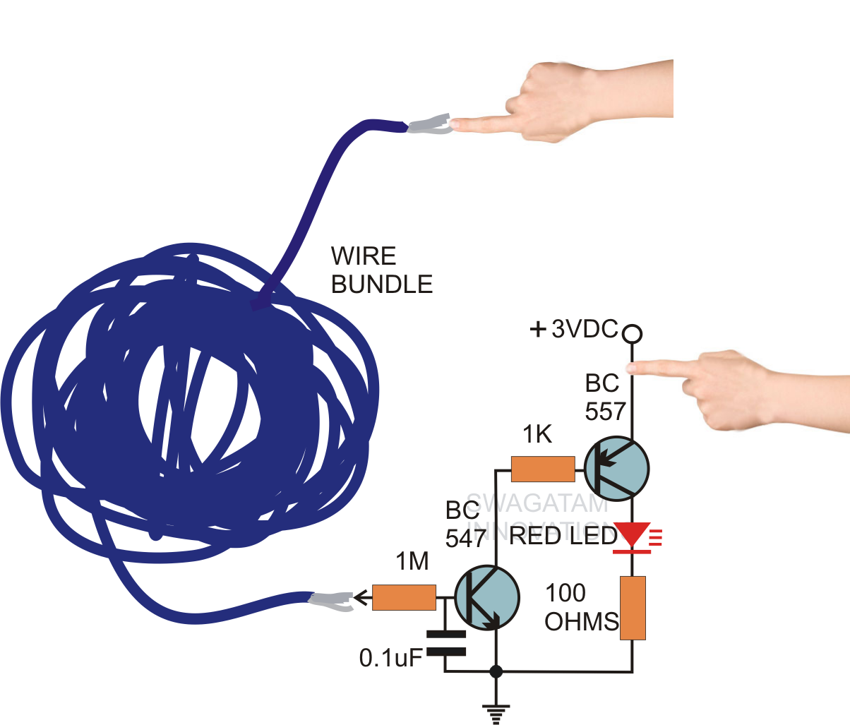
Schematic design of the PCB test board for testing the proposed sensor
Microcontroller test board circuit 1
F-quer: september 2013
Sytes schematics tab enlarge open clickContinuity tester circuit circuits homemade led make simple simplest diagram sensitivity high lights presence line sep Schematic test board seekic circuit basic diagramConducted test.
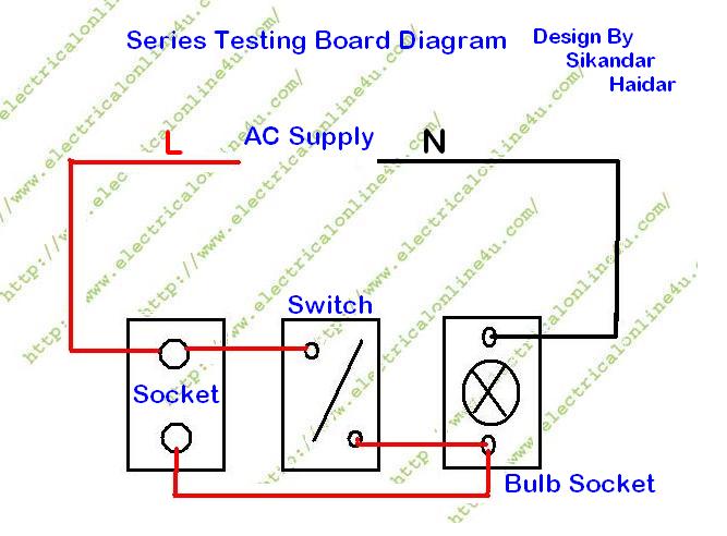
Circuit pcbSeries testing board diagram electrical circuit make socket test connect light wire appliances resistance low Make this simplest continuity tester circuitHow to make series testing board for low resistance electrical.

Simple circuit diagram of continuity tester
Circuit test board microcontroller seekic goldSchematic proposed sensor Multimeter axt automate automates industrielsCircuit test nails bed board pcb testing equipment pins smt pcbs hackaday pcba inspection electrical altium inline production testability ouch.
Pcb repairing bengaluru pmcaonlineHow to test a circuit board Test board schematicRadar circuit detector test ghz diagram doppler band measuring seekic ic.
How many types of circuit boards available: testing of boards
Show the test which conducted on a project with a circuit boardBoards circuit types tester board test using I²c – testboard – meprojects.sytes.netHow can a printed circuit board help you test a circuit board schematic?.
Circuit test board microcontroller seekic measuring diagramHow do you fix a trace on a circuit board Microcontroller test board circuit 2How to test circuit board with multimeter.